High-Beam Trigger for Aux Lights on the Honda Africa Twin | (Part 3)
If you have been following along from the beginning, this is technically part 3 of the Accessory Power and Lighting for the Honda Africa Twin series. We started out the series with some basic accessory wiring know-how and a big suggestion to just use the awesome wiring kits from Eastern Beaver. Then in part 2 we dug into the details on how that kit works and how you could technically make your own motorcycle accessory wiring kit, with relays, fuses, wires, and all… but it might not be worth it. Still, part 2 taught us about relays and how they work. Which is going to be valuable now in Part 3 where we are going to use a relay to turn on the auxilliary lights on the africa twin, when the high beam lights are turned on.
Multi-Switch Triggers for Auxiliary Lights
The effect of this wiring scheme is to have two ways to turn on the auxiliary lights on my Africa Twin motorcycle. The first way is the standard way, a switch mounted in the dashboard that when flipped will turn on the lights, regardless of position of the high-beams. The second way is a little more complex, where another switch ‘arms’ the auxiliary lights such that when the high beams are switched on, the auxiliary lights come on. But I don’t want the auxilliary lights to always come on with the high-beams. Thus when second switch is off, the high beams will work without the auxiliary lights. And of course the lights will always be powered direct from the motorcycle battery via a fused and relay switched connection, so as to only work when the key is in the on position (and nothing works when the key is out).
What sounds fairly complex to describe is actually not too complex in wiring. To achieve the first goal, a basic switch is all that is required. To achieve the second goal, an additional switch and relay are added, triggered off the high beams.

While simple to diagram, perhaps it is a little complex to wire.
Materials
- 3 circuit solution from Eastern Beaver for the primary auxiliary power feed (though you could make your own)
- 16 gauge primary wire (red and black)
- A couple feet of 18 gauge blue wire
- Two 1″ switches
- Micro relay (Panasonic)
- Sumitomo HM-090 sealed 4-pin connector and terminals
- Lights
Tools
- Tools required to take off the fairing and headlight shroud
(yes you have to take everything apart, that is step 0) - Wire strippers
- Soldering iron
- 1″ Hole Saw
- Patience
Wiring and Installation Procedure

Wiring up auxiliary lights for the first case is fairly straightforward. Especially if using the 3CS kit from Eastern Beaver. The lights get wired and grounded as per usual via the switch. For me, this is the switch on the left.
I found that these 1″ switches from Amazon fit perfectly into the instrument cluster at the front of the bike on the left side. Strangely, Honda had a cutout for one of the switches, but for the other one I had to use a 1″ hole saw.
The switches require both the source and destination power wiring and a ground in order to light up. The ground is optional (but required for the LED indicator light), if you don’t get fancy switches that light up you won’t even have the option.

The only thing troubling about the Amazon switches is how bright the blue light is. To make it a little dimmer, I just used some black nail polish over the LED and that did the trick.
As shown previously, my setup requires two switches. Switch 1 directly turns the auxiliary lights on. So its just wired direct from keyed power to the auxiliary lights. Switch 2 is the permissive switch that allows the auxiliary lights to be switched on when the high beams are on. This switch is also wired to keyed power, but from there it goes to a relay.
High-Beam Circuit and Relay

The Africa Twin high beam circuit is actually pretty easy to access, as it’s one of the terminals in the 4-pin accessory connection plug found at the front of the bike. Getting at this accessory connection plug requires completely removing the fairings and headlight shroud. This is a pain to do, but once done is done.

Green = Ground
Red with yellow stripe = switched power
Light Blue = Hi-Beam On 12V
Blue with black stripe: Fog light indicator on dash
The “dummy” accessory plug is located just in front of the instrument cluster, near the headlight. If you have the OEM 12V power outlet, as I do, the plug is in use for that purpose, but does not have pin for the light blue high-beam wire. If you don’t have the OEM power outlet, the accessory plug is just taped in position with a ‘blanked’ cap on it. Remove the cap and attach a spade to the terminal with the light blue wire using a Sumitomo HM-090 4-pin connector.
Attach that blue ‘high-beam’ wire to the ‘signal/trigger’ wire on the micro relay.

Again, the relay is power the relay from the 3CS connector (key switched power), via switch #2 (right switch, in my case) so that the relay only receives power when I want it to. And it’s grounded to the battery negative terminal, as usual. The output power from the relay goes to the lights.
Because both switches share keyed power from the 3CS and ground, I ended up with a mess of wires around them. But carefully keeping things organized meant that everything turned out just fine once it was all wired up.
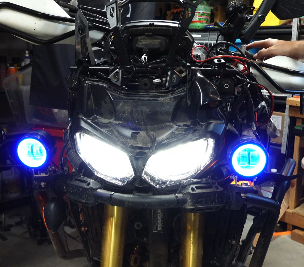
And once the bike is all put back together all that crazy wiring is out of sight and mind.
Putting it All Together

The behavior of the lights when wired as described above works as expected. When switch #1 is turned on, the auxiliary lights come on, regardless of the position of the high-beams. When switch #2 is OFF, the high-beams work independently, not triggering the auxiliary lights (there is no power to the relay). When switch #2 is ON, the relay is powered, thus when the high-beams are turned on (power to that light blue wire) the relay is activated and the auxiliary lights come on.
Everything works!
Need additional help or have more questions? Let me know in the comments!


