
Sprinter Adventure Van Build – Electrical
There is a ton of information out there on how to correctly do the electrical for your van. I read a lot of it. My conclusion: there is a lot of ways to skin this cat and, like many things on the internet, everybody disagrees with each other on the “best” way to do it. In the end I chose the method that seemed the most straightforward to me. So far it is meeting my needs.
Summary (TL:DR):
Get a fuse box and a lot of wire. Choose the wire gauge wisely based on the circuits you are going to run. You can run just the positive terminal and ground to the body if you are not interested in ever “closely monitoring” your power usage. If you want to monitor your usage to a high level of certainty, run the grounding wires back too. A 6 circuit fuse box was not enough for us. We had to upgrade to the 12-circuit mid build. It really isn’t that complicated once you get down to it.

Tools:
- Wire cutters/strippers
- Crimper
- screw driver
Materials:
- Blue Sea Systems ST Blade Fuse Block – 12 Circuits (or 6, if you dont have a lot) with Negative Bus & Cover
- Primary Wire, in multiple colors (or just red and black) – Gauge varies 12 gauge for light applications, 2 gauge for the battery to battery connections
- Wire Terminal Connection Multi-pack (crimper works well, stripper – not so much)
- Simple Battery Voltage Monitor – nothing too fancy
- Another battery: UPG AGM battery – again, nothing too fancy – but recommend a sealed AGM battery for sure, if inside the cab, like mine. 100 AH.
- Various types of sockets throughout the van. USB and Cigarette Style 12V+
- Various types of switches for power control
- Master kill switch: Blue Sea Systems 300A On/Off Battery switch
- Lights for the headliner and the cargo area (under the bed)
- Mega fuse – 100A – buy at least 2 so you have a spare
Reference: (the usual suspects)
- SprinterVanDiaries – great write-up as usual – one I really took to heart
- Dirt Devil’s build post – lots of good info in this thread, including a good schematic
- Another great forum thread – with lots of opinions
- The whole charging from the factory alternator debacle – more strong opinions.
- Info on connecting to the factory OEM auxiliary battery
- BlueSea Circuit Wizard – brilliant! They have an android app too! Invaluable for choosing the correct wire gauge.
Procedure:
Doing the electrical is a pretty tedious process of running wires, stripping wires, crimping wires, and connecting things together. It can be very dangerous, but in the end I thought it was pretty simple. As I said before there are a lot of opinions about the “right” way to do things. I chose the simple path that made sense to me and that seems fine for now. I have protected everything with fuses and used appropriately gauged wire, so I am hopeful that it is safe and secure for many years to come. That being said, I am not an electrical engineer, contractor, installer, anything. I am not really giving advice here, just stating what I did for the record.
I started out with a very detailed electrical diagram:

That pretty much sums it up. 2 batteries wired together. A fuse box and solar panels. The solar panels I will talk about in a different post. I’ll try to describe some of the salient details here.
We ordered our sprinter with the factory auxiliary battery. I believe this simplified things, since I already had a factory battery isolator (ACR) to charge the auxiliary batteries from the factory alternator, while keeping them isolated when the vehicle is not running (maintaining the starting battery for just starting, leaving the auxiliary batteries for auxiliary things). So the detailed V1 diagram above is a little misleading – there are more batteries and some more hardware involved. So, in order to make sense of things I have developed V2 for reference. Note, I created this version after everything was already wired up and done, sitting here creating this blog – so much to say, it isn’t a required part of van wiring to make a fancy diagram. The tool available online from DigiKey is pretty fun to play with though. Even if I didn’t understand most of its functionality. V2 attempts to be more detailed than V1, but my understanding of the concepts hasn’t really increased that much. So don’t pay any attention to the factory charging relay, alternator, starter battery etc. I don’t really know what is going on there – you can find more information in the Sprinter Bulletin Here: aux connect. My main point of interest was at the “2. Aux Battery Electrical Tap”. We didn’t mess with anything else.

As shown in v2 of the wiring diagram, we went with 2 auxiliary batteries. The OEM auxiliary battery, which is located under the hood, in the spot that you would usually find a starter battery on other vehicles (I am told the vehicle starter battery is located under the driver side floor boards, but I have never actually gone looking for it) and another auxiliary battery we purchased separately placed under the passenger seat, next to the Espar heater. No I am not worried about the proximity of the battery to a heat source. We have run the heater continuously for several nights without incident. The strap holding the battery to the wall does a good job of providing separation between the hot parts of the Espar heater and the soft (plastic) parts of the battery.

in the passenger
seat pedestal, next to
the Espar heater
For battery selection, I went with cost effective. The OEM auxiliary battery appears to be a 95 amp-hour (AH) AGM battery, so I tried to match this selection. There was a lot of talk about how having matching batteries can improve battery performance over time. This seamed reasonable to me so that’s what I did. But I didn’t feel the need to purchase a very expensive name brand AGM battery. I found a 100AH battery on amazon that had good reviews and it has worked well for me thus far.
I did a whole ton of reading about why or why not to wire your batteries directly to the factory alternator (via the automatic charging relay, of course). People do all kinds of things here including getting another alternator, avoiding the alternator and relying on solar/generator, converting the alternator to AC then back to DC via a double inverter… In the end I couldn’t find any reason not to do it the simplest way. The alternator in our sprinter is designed for 225 amps – you could literally run an arc welder off the alternator. I found it hard to believe that it couldn’t handle charging a second battery (or more). It appears that a lot of people have drawn this conclusion as well, so if it’s a bad choice I will have lots of miserable company. Of course, I am far from an expert on this kind of thing – so READ UP and make YOUR OWN informed decision.
The auxiliary battery terminals for both of our batteries come to under the drivers seat. There is a plastic conduit that runs between the two front seat pedastals that we used to convey the 2-gauge wires and protect them from foot traffic in that area. To get it it, it requires removing the floor liner, removing the rear heater vent (if equipped) and prying up multiple plastic tabs. We ran a pilot wire through the plastic conduit to make running a few wires back and forth easier. Duct taping the wire to be pulled onto the pilot wire allowed us to pull the wires through, having enough additional length on the pilot wire allowed us to pull the pilot wire back so as to allow multiple pulls through the white plastic conduit to the driver’s seat pedestal.


There, on the back end of the driver’s seat pedestal is a terminal block with a copper … thing. The upfitter’s guide says that this is a fuse. If it is, it’s not like any fuse I have ever seen. I got rid of it and replaced it with a 100A “mega fuse”. This provides a baseline of protection for all of my downstream circuits, my battery wiring, etc. Because the driver’s seat pedestal is crowded with all kinds of wires that I was afraid to mess up, I didn’t do much more wiring in this area (save for connecting a “master ground wire” (2-gauge) to the chassis ground lug in this location, as well). Everything else I put in a (not-so) little wooden box built and bolted behind the driver’s seat pedestal. This serves to house the other electrical gear, including the kill switch, solar charge controller, main fuse panel, amp and other accessories for the sound system, and a whole bunch of wires running everywhere like spaghetti.
The electrical box serves as pretty nice seat, when the van is parked and the driver’s seat can be moved and leaned forward. We added some padding to the lid which made it quite comfortable. Inside all the electrical gear is kept mostly organized and out of the way of damage from movement within the van. From there it is also an easy and clean jump into the B-pillar for wires going back into the main cabin of the van. For wiring, we didn’t do anything fancy, just ran wires through the cavities in the van frame to the various points of use. Lights, usb power, 12V+ power, fan, etc. Its pretty straightforward once you get into it. We tried to utilize different circuits for all the various ‘categories’ of equipment to keep things straightforward.
All in all I think it turned out pretty well. We are very pleased with all the various electrical items that we bought and I wouldn’t hesitate to recommend them for other builds. For the fuse box, I will mention that we started out with the 6-circuit panel and ended up running out of space – so we upgraded to the 12 circuit panel. Maybe that’s a recommendation for better planning of your circuits before diving into the project and purchasing the materials. Below are some additional photos of the electrical box and other electrical accessories “for the record”.

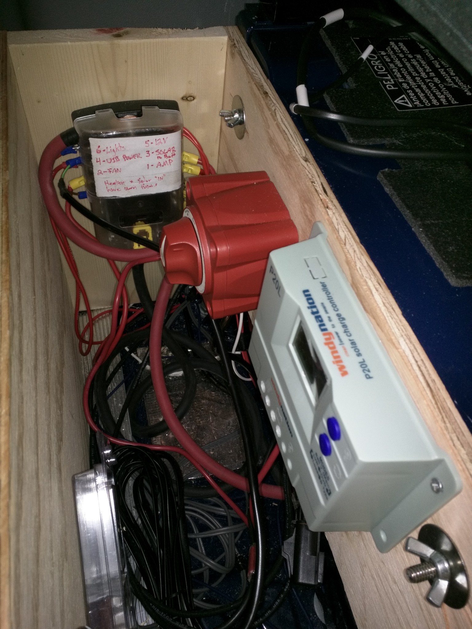
Electrical box, including (from left to right): fuse panel, kill switch, and solar charge controller. 
Charge monitor, showing actual voltage as a fraction of “full battery” voltage 
Electrical box behind the driver’s seat 
wiring for the lights. you can also see a two rocker switch that controls the “cabin” lights and the bedroom lights. Overall the lights are awesome, and very VERY bright. 
Headliner photo showing the lights and fan installed and on. Very impressed with how well these cheap LED lights are working out. 
Additional 100AH battery in the passenger seat pedestal, next to the Espar heater


kudos on your write up … really appreciate your simple approach. I am at a similar crossroads…have aux battery, thinking of more power. Using the space under the passenger seat, using alternator combined with solar to charge, and not paying $1000 for a 3rd battery all sound perfect. Winter project! Before I dive in, I need to figure out my aux system….I couldn’t figure out the right tie-in point, so tried the wire direct to aux battery, before the relay….suspect I may have burnt out my relay. Testing to come soon. Anyways, not really a question (yet), just a “job well done” comment.
Wiring direct to the aux battery at the battery terminals (under the hood) should be fine. Of course fuses are a good idea, but the aux battery is itself on the correct side of the relay for powering aux devices. So I am not sure how you would have blown the relay wiring direct. I have a couple USB charging ports wired direct to the aux battery (with a fuse). Its not an elegant (or long term) solution, but it beat running longer wires across the driver area at the time.
Hopefully you found the factory terminals under the driver seat (on the back of the seat pedestal, facing forward). They look like this (but with a black plastic over them). The rest of the details on that (including adding a master fuse) should be in the main write-up.
For testing, you should be able to figure out fairly quickly if the relay is blown (though I am not sure why it would be). Check the voltage across the aux battery with a circuit tester when the car is off. It should be around 12V. Then start the vehicle and test the voltage again. Charging voltage should be 13+V, so you should see that reflected in the test. If it doesn’t change – then yes, relay is not relaying. If you think both batteries are always bridged you could check the resistance between the two positive wires (unhooked from their terminals) of your main vehicle battery and aux battery. If you get 0 ohms, the wires are isolated. If you get any reading of resistance (or infinite) then they are not isolated. you could also put a load on one battery and see if you get a voltage dip on the other – might be easier depending on what you have available.
Sorry if you know all of this already. Just trying to be helpful.
Also – I was curious so I found this good write-up on testing battery isolation: https://stephenstuff.wordpress.com/2013/04/11/dual-battery-system-testing/
I like their idea of testing the isolation under load by turning the headlights on. That should be easy! Check voltage across both batteries. Turn headlights on for a few minutes. Voltage should drop on the vehicle battery but remain the same on the aux battery.
Really appreciate the reply! And no, don’t know all that….figuring this out as I go! I have the MB guide to connecting power to aux battery, but it didn’t seem to be right….I disconnected the aux battery to test it, the post I was supposed to connect to still had power. I suspect my aux battery may not be wired to specs. So I connected my house power fuse box to the connection post where the lead from aux battery connects in under the seat — more or less a direct connection to aux cord. Unsure if that may have screwed something up, as aux battery does not appear to be charging right. I have to remove the seat again and see what’s what. The sprintervanusa fellow (dieselfumes) also sent a test: disconnect the aux connection on relay, see if it gets power when turn ignition on (after a brief built in delay). So will see soon.
Questions:
For your wiring: did you connect your 3rd battery positive to the same post where the aux positive cord comes in from the engine compartment?
3rd battery negative: did you run a wire to the driver side vs just attaching to the frame under passenger seat?
Solar charger: do I have it correct that the positive is just connected to your house fuse box, the trickle charging runs back to the battery from there? (which seems “backwards” for some reason, but makes sense!)
Heater power: did you run its wiring to your fuse box and back? Or just run it direct to the battery beside with inline fuse? (repeat question from your other webpage)
Sorry if these are dumb questions! Really appreciate the advice.
Good questions John. Sorry for the delayed response. Hopefully you got these figured out.
1. all my “house” batteries connect together under the driver’s seat
2. battery negatives terminate to the frame at locations where they are located. All house electrical items negative terminals terminate at my power meter shunt and then combined go to the frame.
3. solar charge controller goes to “house” fuse box, yes. At 20 amps its quite a bit more than a trickle.
4. Yes, heater goes to my “house” fuse box as well.
Hope this helps. Happy building!
Thanks for posting….really appreciate your simple and straightforward approach. I have an aux battery and considering adding a 3rd … done some quick googling and quickly overwhelmed by all the technical info, conflicting opinions, and tendency towards overbuilding in SprinterLand 😉 Your plan meshes with my ideas/hopes: use space under passenger seat, use alternator to partially charge 3rd battery, not spent $1000 on 3rd battery. I have been toying with idea of solar….your idea of a passive trickle charger on top may push me over the edge. I don’t know if i have any questions (will soon I suspect) but mostly just kudos. Before getting into this: I need to do some figuring out on my aux relay and house fusebox set up….I tapped into aux at non-recommended point, suspect I may have blownmy relay … testing to come soon.
Does the OME AUX BAT feed into the factory fuse blocks? Couldn’t you sue that for power? Also where did you find the headliner?
2017 sprinter 3500 ext high roof
The OEM auxiliary battery does not feed into the factory fuse blocks. it is completely auxiliary. The headliner came with our crew van.
What did you use for cheap led lights? Thanks
– Will
See links in post: Lights for the headliner and the cargo area (under the bed)
Hello, in you “V1 of the Van Electrical Wiring Diagram” you show all of your grounds going to the same location attached to the chassis. How did you connect all of your negatives to one location? Did you use a negative “bus bar”? Second question, where do you connect the battery voltage monitor? Thanks!
Mike – The Blue Sea Systems ST Blade Fuse Block that I used has a negative terminal block included in the unit. So essentially you are correct – negatives were routed to the integrated bus bar on the fuse block and then all routed to the factory negative terminal under the driver’s seat. The battery voltage monitor I use is just a super cheap and simple lcd screen with voltage readout. It is simply wired into one of the terminals on the fuse block. This isn’t a fancy battery monitor that counts the number of amps in and out – just gives the voltage and lets me know if I am doing damage to my batteries by running them too low (preferably before I do damage to my batteries).
Hope this helps!
Great and helpful site. I’m planning to as a second aux battery from passengers seat. How do you connect #2 battery to arc? Did you stack both aux cable lugs onto the arc terminal? Or did you run both aux battery +cables to battery selector switch and then selector switch to acr? Thanks for the reply.
Scott – I am not sure I am understanding your question completely. Per my wiring diagram I put both the OEM aux battery and my additional aux battery to the positive terminal just ‘upstream’ of the master fuse (located under the driver’s seat). And then I grounded the additional aux battery to the factory provided ground terminal also underneath the driver’s seat. In this way, both batteries get charged via the alternator when the van is running and both batteries are drawn off equally. I don’t have a selector switch for the batteries. They are either both on, or both off. Hope that makes sense?
Thank you for the helpful post. Maybe you can answer a couple questions for me.
Why did you use such a heavy gauge wire to go from the 100amp fuse to the fuse block? Wouldn’t something like 6 awg work?
What gauge wire did you use to wire the lights?
When wiring the lights in parallel, what type of crimps did you use to tap into the long run of + and – wire?
Thanks in advance.
Tim
Hi Tim, Sorry for the delayed response – been traveling! A great resource for determining wire size is Blue Sea Systems – Circuit Wizard. I relied on this resource quite a bit for my electrical build. I can’t remember the exact parameters (length and amps) I used to determine the wire gauge, but my goal was to run the wires once and never touch them again. So that’s how I ended up with the 2-gauge running between the front seats (that and it was probably on sale or something at the time).
For the lights I believe I used a mix of 12 and 14 gauge wire. Again, I would utilize the blue sea calculator to be sure, based on your operating amps and wire run lengths.
For “teeing” off the main lighting wire runs, I pulled back the wire insulation and manually soldered on the branch lines. Then I taped them up with electrical tape. A more professional way would probably be to cut the main and install heat shrink tubing. Then solder everything up and insulate it with the heat shrink tubing. However, I haven’t had any problems so far with my setup.
Hope this helps!
Have you had any issues adding a second battery in parallel with the factory aux battery? I heard a rumour your couldn’t do that. Can you help me with this?
Great site!!
Thanks Tyler. I have heard that rumor as well, but never found any real ‘science’ to back up that claim. I am not an electrician or an expert in most things automotive, and was unconvinced this was actually a problem. I believe the concern is with how the Sprinter’s main computer (ECU?) controls charging from the alternator. Apparently there is some fancy electronics that go along with this that having lots of batteries on the auxiliary side may mess up. However, in my research the factory AUX battery appears to be installed with a typical ‘cut-off relay’ (Also known as an ACR – See this link) so I have a hard time believing that using the factory ACR is any different than installing a separate ACR. Lots of other DIY sprinter camper folks have run some kind of ACR setup, to connect to the sprinter’s alternator for house battery charging. I decided to follow their lead (which may be ill advised by some). To date I have had no problems with my approach. And from what I can tell, others haven’t reported any troubles with theirs either.
I found this post and several others in this thread by DDunaway pretty valuable, data wise. Worth looking into.