DIY Wireless Phone Charging Motorcycle Mount
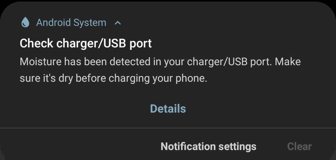
Wireless phone charging is pretty sweet and the charging pads are fairly inexpensive. Vibrating cables (or worse… phone charging ports) to death while mounted on an adventure/off-highway bike is not awesome. Not to mention the risk of damage from plugging in a wet charging cable. But there is a fairly simple solution: A wireless charging motorcycle mount!
Summary TL:DR
Hacking an inexpensive wireless phone charging pad and sticking it to a motorcycle phone mount is a pretty straightforward project. Just break open the charging pad and extract the electronics and coil. Adjust the wiring as appropriate and waterproof the assemblies using nail polish and/or Silicone 2+. Wire it up (to a USB port or stepdown voltage converter) and you’re good to go!
Also, if you don’t want to make your own – you can buy one (but where’s the fun in that?)

Mount and Charger Requirements
I use my phone as my navigation device while riding and its nice to have the screen always on for that (don’t want to have to wake it up, every time I need directions). Of course, in bright sun, with full screen brightness that also uses up a lot of battery. It also means that my phone is exposed to the sun, wind, and rain – the assembly needs to be fairly waterproof. I do a fair amount of adventure/off-highway riding. The roads and trails can be pretty bumpy – so the mount and charger need to be pretty robust. All summed up, here are the requirements:
- Provide enough power to charge the phone with the screen on at full brightness.
- Be generally waterproof (at least to the same standard as the phone itself)
- Be rugged enough to withstand constant vibration.
Tools
- soldering iron, wire strippers, wire cutters, and the usual electrical gear
- screw driver
- heat gun
- caulking gun
Materials
- Wireless charging pad (10 to 15W) – there are lots of options available, I just picked one.
- Motorcycle Phone Mount – I have been using the x-grip for several years and have been happy with it’s performance (though it’s a little tough to get my phone [Samsung Note 9] in and out), but there are options such as the Tackform and Quick Grip, which also receive rave reviews (my wife has the Tackform phone mount and loves it)
- stranded electrical wire (18 to 22 gauge is fine)
- nail polish (for waterproofing)
- silicone 2+ (for potting the electronics)
- epoxy or jb weld
- electrical tape
- heat shrink tubing (optional)
- tegaderm medical dressing (for containing the silicone)
- 3M UHB double sided tape
- For reference, my phone is a Samsung Galaxy Note 9, which has wireless charging built in. If your phone doesn’t support wireless charging natively, you can retrofit it with a charging receiver- like this one
Reference
Several folks have done this before and I just followed in their legendary footsteps:
- Wireless phone charger project: waterproof, fast, handlebar mounted, reliable via ADV Rider
- Silicone electronics potting via Hackaday
- Nail polish for electronics waterproofing via GreatScott’s YouTube
The Procedure
I have annotated the photo gallery below with my general procedure for building a wireless phone charging motorcycle mount and have also provided some additional details in the narrative.

The finished product – our goal: A wireless charging pad attached to the Ram X-Grip mount 
1. I started with a 15W wireless charger from Letscom (amazon) 
2. Pop open the plastic casing using a screwdriver (screws underneath the small black covers 
3. Inside is the charging coil and charge controlling PCB 
4. Heat up the back of the charging pad to soften the glue holding the charging coil down 
5. the back of the charging coil and PCB removed from the plastic casing (be careful not to damage the magnet!) 
6. the front of the charging coil and PCB. I wanted more room between the coil and the control circuit 
7. So I cut the wires connecting the two pieces 
8a. And then reattached them by soldering new wires between the two 
8b. good idea to note the orientation of the wires connecting to the PCB. 
9. I used heat shrink tubing to keep everything together and looking good 
10. Using Tegaderm transparent dressings and Silicone 2+ sealant to “pot” the PCB. 
10b. I kept the USB cable plugged in during the potting process, so that the USB-C port didn’t fill up with silicone. 
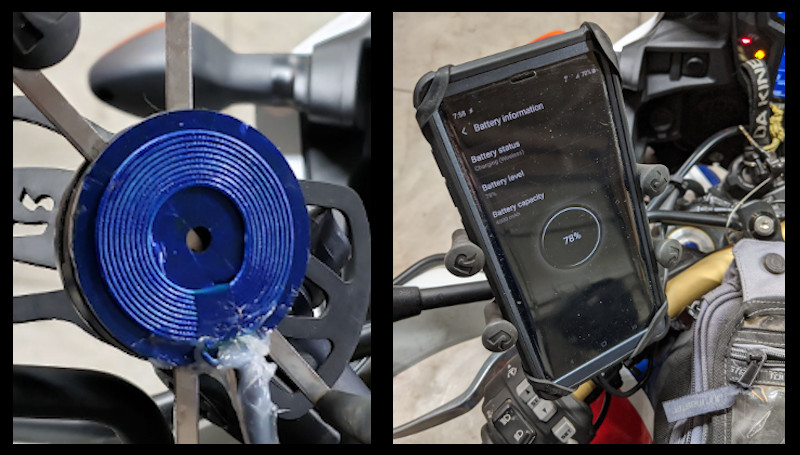
11. I used blue nail polish on the charging coil and magnet. I think it looks pretty cool. 
12. here is the finished product, silicone protecting the PCB and nail polish protecting the charging coil 
13. Because my silicone potting job was so bad, I wrapped the PCB in electrical tape too. 
14. I used 3M VHB double sided tape to attach the charging coil to my Ram X-grip phone mount. Fits perfectly. 
15. the size of the coil fits perfectly on the central section of the X-grip. 
16. For the USB power, I wired a USB charging receptacle into my Eastern Beaver power distribution module. 
17. In order to keep the PCB module out of the way (but still accessible) I velcro’d it to my tank bag (under the map flap).
1. Unbox the charging pad. I went with the “LETSCOM Wireless Charger, Qi-Certified 15W Max Fast Wireless Charging Pad Ultra Slim” because I thought that 15W of power seemed like the right amount (10W recommended by others, 15W must be better?). You can also just order the components, but there didn’t appear to be any savings and the reviews were pretty bad.
2. Hack open the plastic casing. I jammed a screw driver into the side of the charging pad and pried it open. I realized later that there were little philips head screws underneath the black plastic covers on the bottom that would have made disassembly more elegant – oh well.

3-5. Remove the printed circuit board (PCB) and charging coil assembly from the plastic casing. The charging coil is glued to a very lightweight and fragile magnet. Do not try to pry it up with a screw driver! You will break the magnet (I did some damage, but it still seems to work – probably would have been better if I hadn’t cracked it though). For the LETSCOM Wireless Charging unit, the charging coil and magnet assembly is glued to the black casing. I used a heat gun to warm up the adhesive and gently pry it off the back (yes I used a flat head screw driver, but I was gentle).
6-9. Following the suggestion of folks on ADV rider, I separated the charging coil assembly from the PCB. This way I can put the PCB in a safe spot under my tank bag and only have the charging coil directly exposed to the elements. To do this, i simply cut the wires connecting the PCB and the coil and then reconnected them with a longer piece of wire between the two (maybe 2′ long). I soldered these new connections so they are pretty strong and insulated them with heat shrink tubing.
Note: there was also two more tiny unisulated red wires that went “into” the charging coil from the PCB. My only guess is these are part of a temperature control/switch? But I couldn’t really tell what they did from looking at their attachment point on the PCB. I pulled them out of the charging coil and coiled them up on the PCB. They do not appear to affect operation – yet.

10. To protect the PCB assembly, I potted it in silicone sealant. This was new to me, but hackaday has a good write up on how to do it cleanly using 3M Tegaderm (yes, the transparent wound dressing system), which contains all the sealant without making a mess but still breathes well enough for it to cure. And there is also this youtube video, showing how its done. I only had small Tegaderm patches on hand – which made it difficult – but it got the job done. The next time I do this I will use the bigger Tegaderm sheets to better be able to completely wrap the electronics. I kept the USB cable plugged in during the potting process, so that the USB-C port didn’t fill up with silicone, but then unplugged it when I was done, so as to avoid it getting stuck plugged in (I wanted to keep it removable). I cleaned the connector with rubbing alcohol to remove excess silicone.
Note: using the right kind of silicone sealant is important. Apparently some types (type 1) use acid to cure, which will damage the electronics. Silicone 2 or 2+ are apparently safe for electronics. I got mine on amazon, but its also available at most hardware stores.
11-13. For the coil, I used nail polish to reinforce and waterproof this assembly. This YouTube video was pretty convincing that nail polish was the cleanest and lowest profile way to go. I also put a think layer of epoxy on the backside of the magnet for a little extra strength and rigidity as well as epoxying the cable connection to the charging coil, just so there was some extra stiffness there.
14-15. I used 3M UHB tape to attach the charging coil assembly to the plastic plate on the Ram X-Grip phone mount. It fit perfectly. I oriented it so the attached cable is pointed down.

16. To provide USB power, I wired in another USB charging port underneath the seat of my Honda Africa Twin. I could have used the 12V power port up on the dash, but the intent here was to have a more water resistant setup with this – and I just don’t trust that port up front as much. So having another USB port under the seat can serve this purpose (and others if need be). And then I can also have a backup system (utilizing a USB adapter in the 12V port) in case this goes bad.
I wired a USB charging receptacle into my Eastern Beaver power distribution module, as described in this post.

17. Lastly, I velcroed the PCB piece underneath the map flap on my tank bag. This seemed like a good place, out of the direct elements, but still accessible if needed. And is a good intermediate spot between the USB charging port underneath the seat and the phone mount.
After a few test rides wireless charging is working perfectly and I am very happy with the results. The phone continues to charge, even when the screen is on at full brightness and all components appear to be stable during transit. Will update as testing continues.
Complete gallery of each step:
The finished product – our goal 1. I started with a 15W wireless charger from Letscom (amazon) 2. Pop open the plastic casing using a screwdriver (screws underneath the small black covers) 3. Inside is the charging coil and charge controlling PCB 4. Heat up the back of the charging pad to soften the glue holding the charging coil down 5. the back of the charging coil and PCB removed from the plastic casing (be careful not to damage the magnet!) 6. the front of the charging coil and PCB. I wanted more room between the coil and the control circuit 7. So I cut the wires connecting the two pieces 
8a. And then reattached them by soldering new wires between the two 8b. good idea to note the orientation of the wires connecting to the PCB. 9. I used heat shrink tubing to keep everything together and looking good 10. Using Tegaderm transparent dressings and Silicone 2+ sealant to “pot” the PCB. 10b. I kept the USB cable plugged in during the potting process, so that the USB-C port didn’t fill up with silicone. 11. I used blue nail polish on the charging coil and magnet. I think it looks pretty cool. 12. here is the finished product, silicone protecting the PCB and nail polish protecting the charging coil. 13. Because my silicone potting job was so bad, I wrapped the PCB in electrical tape too. 14. I used 3M VHB double sided tape to attach the charging coil to my Ram X-grip phone mount. Fits perfectly. 15. the size of the coil fits perfectly on the central section of the X-grip. 16. For the USB power, I wired a USB charging receptacle into my Eastern Beaver power distribution module. 17. In order to keep the PCB module out of the way (but still accessible) I velcro’d it to my tank bag (under the map flap).


